Computer Architecture
Formally, a computer is characterized by its instruction set architecture, which is an abstract entity (meaning the implementation and design of the computer itself is irrelevant) that defines the computer from a programmer’s POV
This ISA consists of three parts: the register set, instruction set and addressing modes
The ISA is also embodied by Assembly, a programming language at the heart of the computer
Computer Organization
Since ISA is the abstraction of the computer, the organization is how that ISA is implemented
You can think of the ISA as an initial plan for a building and the organization as the blueprint, so even if the blueprint changes slightly, the idea (ISA) stays the same
- Today, organization is called microarchitecture
Theoretically, architecture and organization are independent
Computer Structure
The structure of a computer is how the individual components of a computer connect with one another
The computer structure almost always consists of a CPU, which reads and executes command, but some modern computers will also include a cache memory on the CPU chip to speed it up
Below is an example of a computer structure
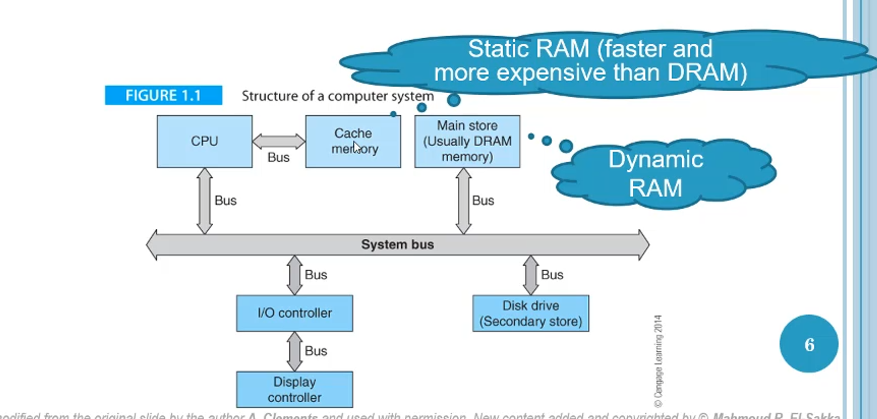 disk drive, DRAM and cache memory
The busses act as roads that move information across components in a sort of data highway system
Process Register
A process register is a memory element that holds a single unit (word) of data
These registers are specified in the number of bits it holds, which is almost always 2^something
- Nowadays, this is mainly 32 bit and 64 bit
Each processor has a specified number of registers, which only differ from words in memory in their speed, since registers are in the CPU itself
Computer Type
Two types of computer exists: dedicated and general-purpose
Dedicated computers only solve one problem, such as a dedicated bitcoin mining rig
A general-purpose computer, however, can be programmed to solve any problem, which applies to most home PCs
The main difference comes with being able to change the program of a general-purpose computer, which dedicated computers don’t have
Programs
Typically, how you’d write a program in Java is you’d do something like this
int z = x + y;
However, in Assembly, which the CPU actually uses, this would have to be split up a bit like this
LOAD X
LOAD Y
Z = X + Y
STORE Z
STOP
- Note that this isn’t actual Assembly
The start of each of these lines (called events) is dictated by the CPUs clock (a stream of pulses sequencing all operation in a computer)
- This clock makes sure that processes run in sequences
The clock is measured in Hz and also the width of the pulse, which is $1/T$
For example, 1 MHz is 1 microsecond (10^-6) and 1 GHz is 1 nanosecond (10^-9)
Below is an example of what’s happening behind the scenes
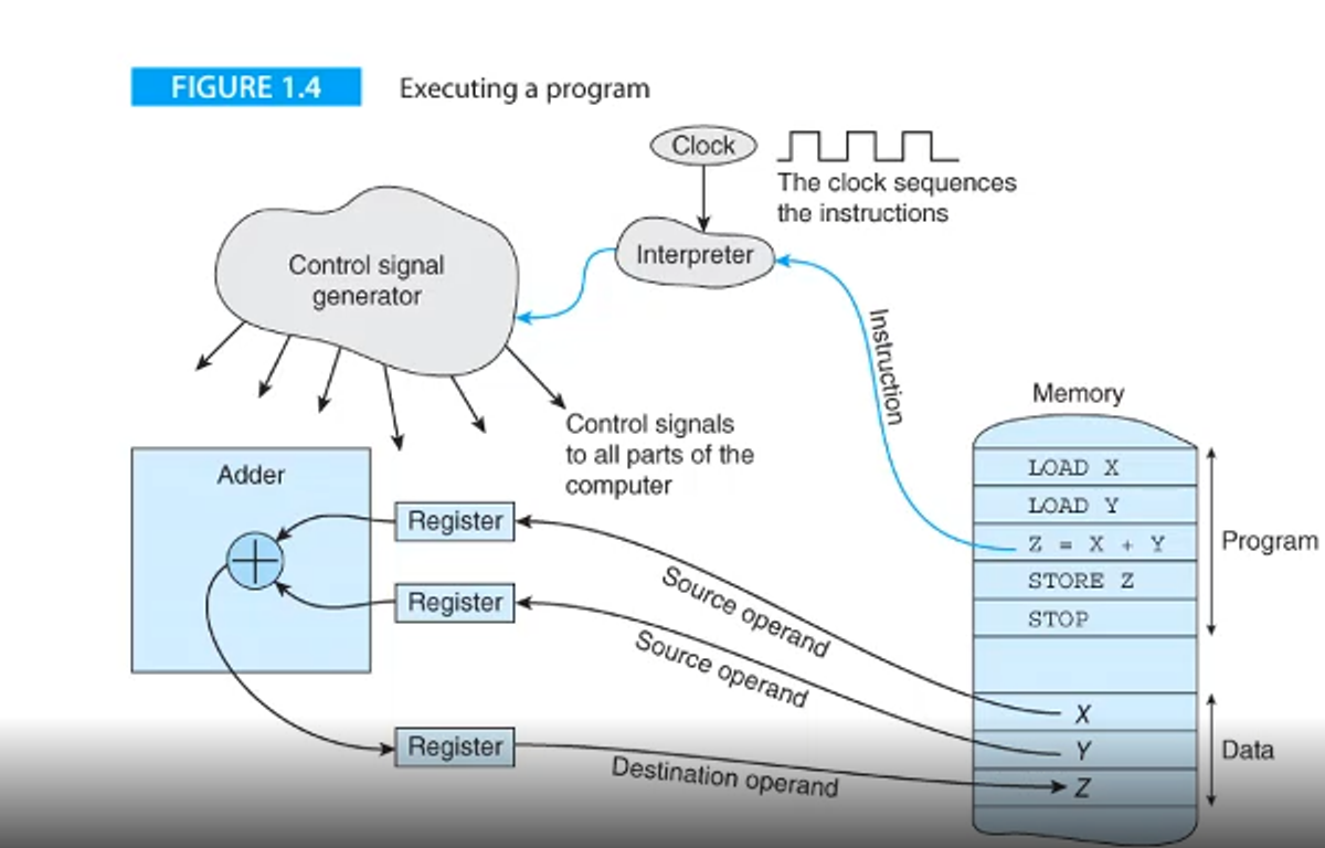 control signal generator
Then, the signal is sent off to the adder, which pulls x and y into the register from memory
Finally, the output z is placed into a register and sent off to z in memory
All in all, this program takes up 8 words in memory, which is important since memory is the bottleneck for any program in this computer structure
Intro to the Computer
To introduce the computer, we should talk about a problem
This problem is fairly simple; find the longest sequence of consecutive digits in a string, like so
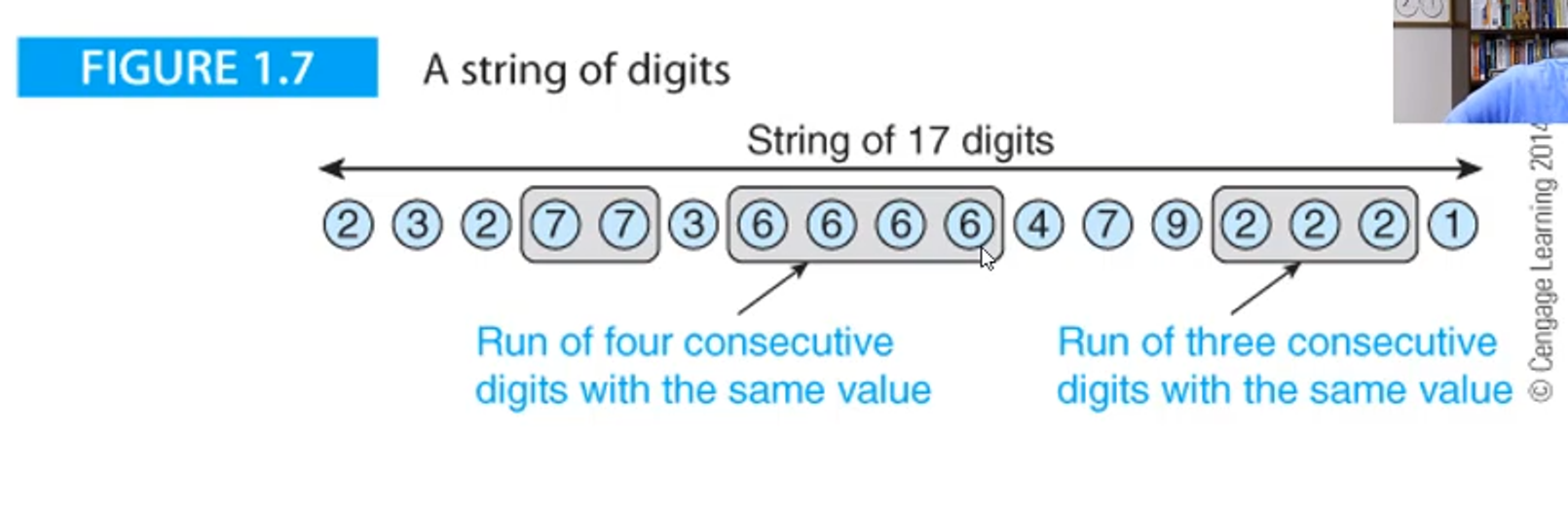 consecutive digits or not in a run of consecutive digits
From here, we will transition between these two states, which we can examine using what’s called a state diagram
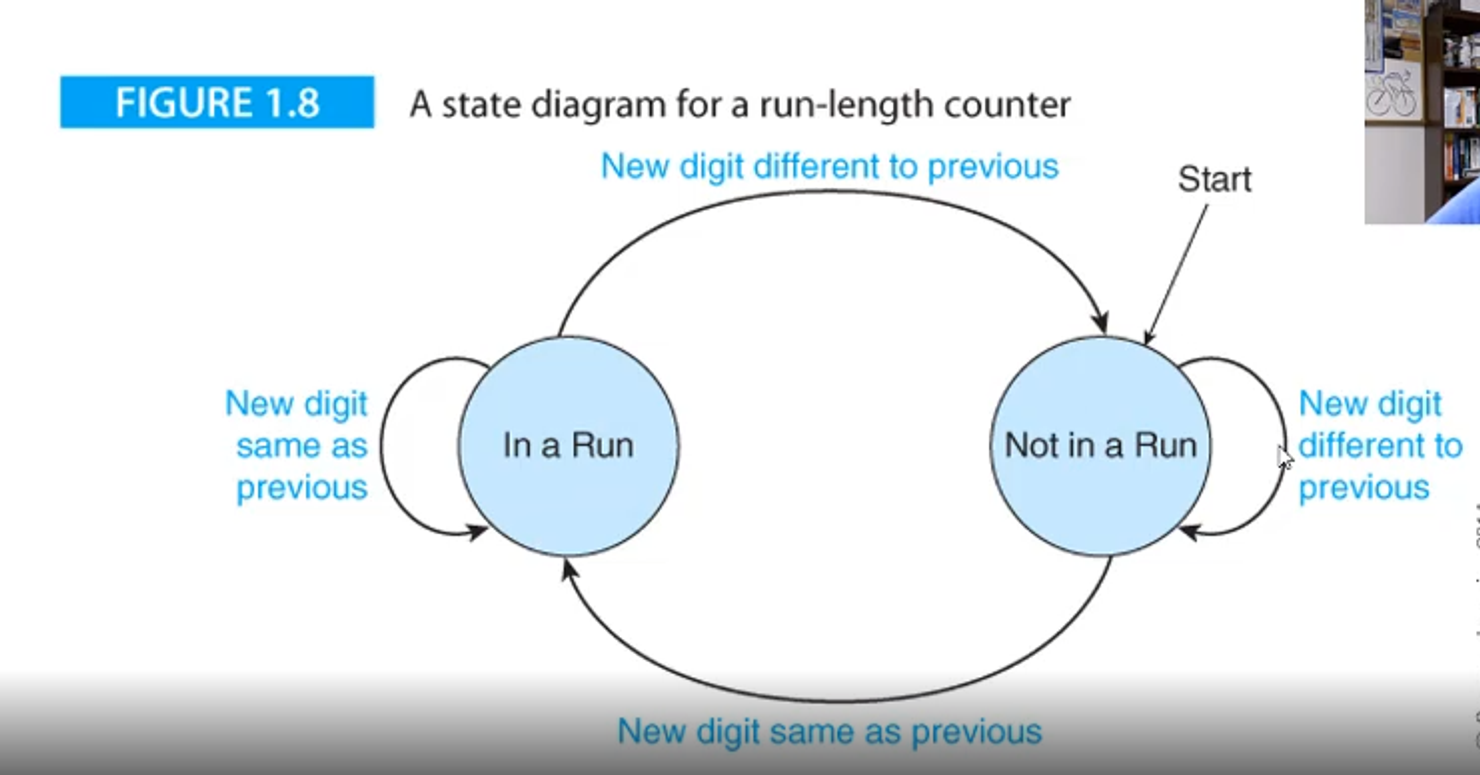 go back to NR for the second, third and fourth digits
At the fifth digit, we recognize that the digit is the same, so we change the state to in a run (R), but then go back to NR by the sixth digit
This process continues until we hit the end of the sequence of strings

We also need to keep track of which run is the longest, so we’ll do that as well
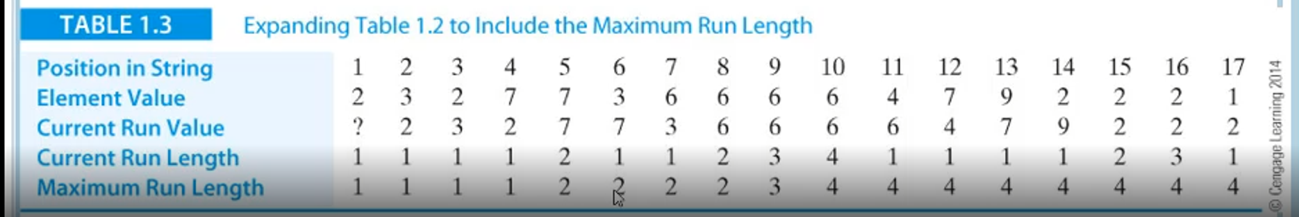
Now that we have an algorithm, we can write it out, first by making some variables
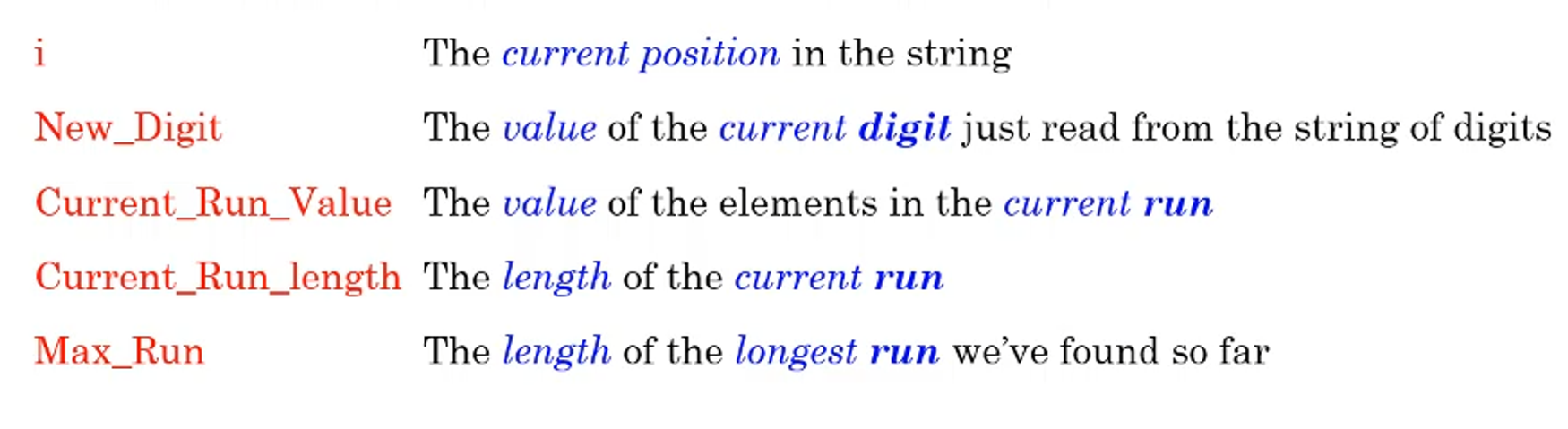
From here we can develop some simple pseudocode to solve the problem
Read the first digit in the string and call it New_Digit
Set the Current_Run_Value to New_Digit
Set the Current_Run_Length to 1
Set the Max_Run to 1
REPEAT
	Read the next digit in the sequence (i.e., read a New_Digit)
	IF its value is the same as Current_Run_Value
		THEN Current_Run_Length = Current_Run_Length + 1
		ELSE {Current_Run_Length = 1
					Current_Run_Value = New_Digit}
	IF Current_Run_Length > Max_Run
		THEN Max_Run = Current_Run_Length
UNTIL The last digit is read
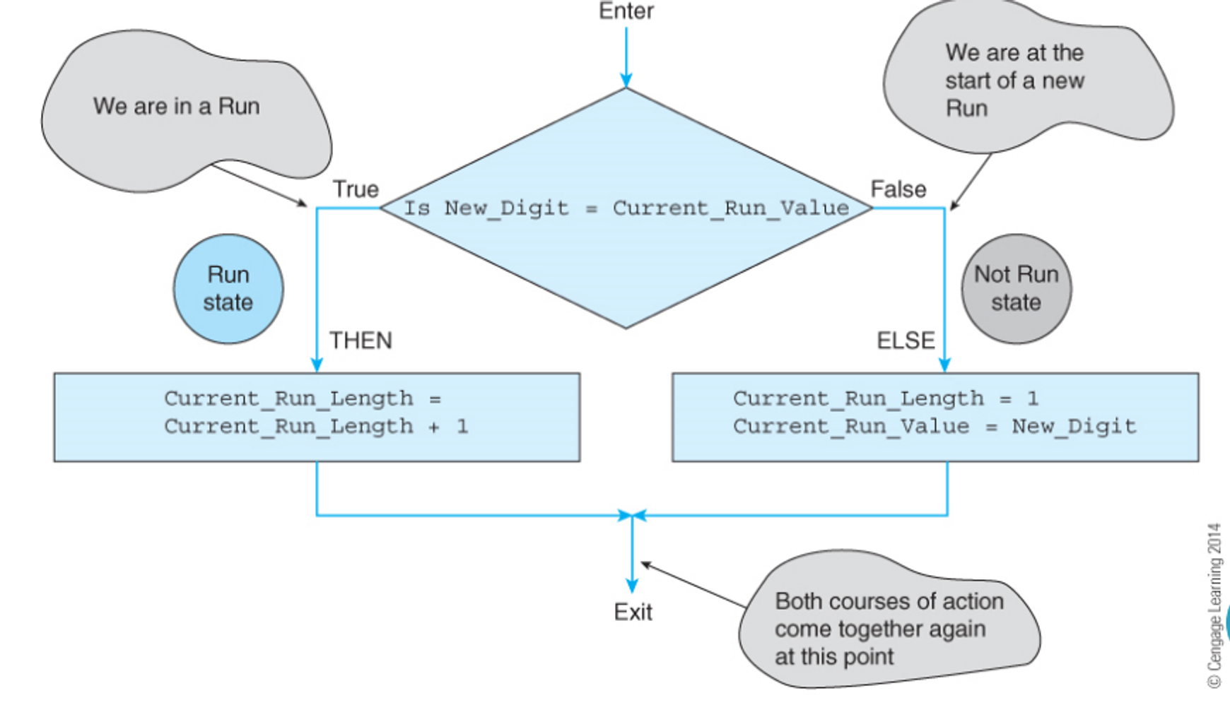
From here, we will introduce a flowchart, which is basically a diagram of pseudocode
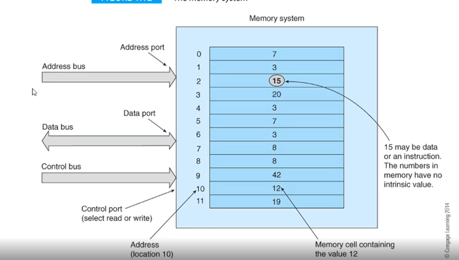
From here, we store everything we need in memory, with all information being turn into machine code (0s and 1s), where the CPU can’t differentiate between a value and an instruction
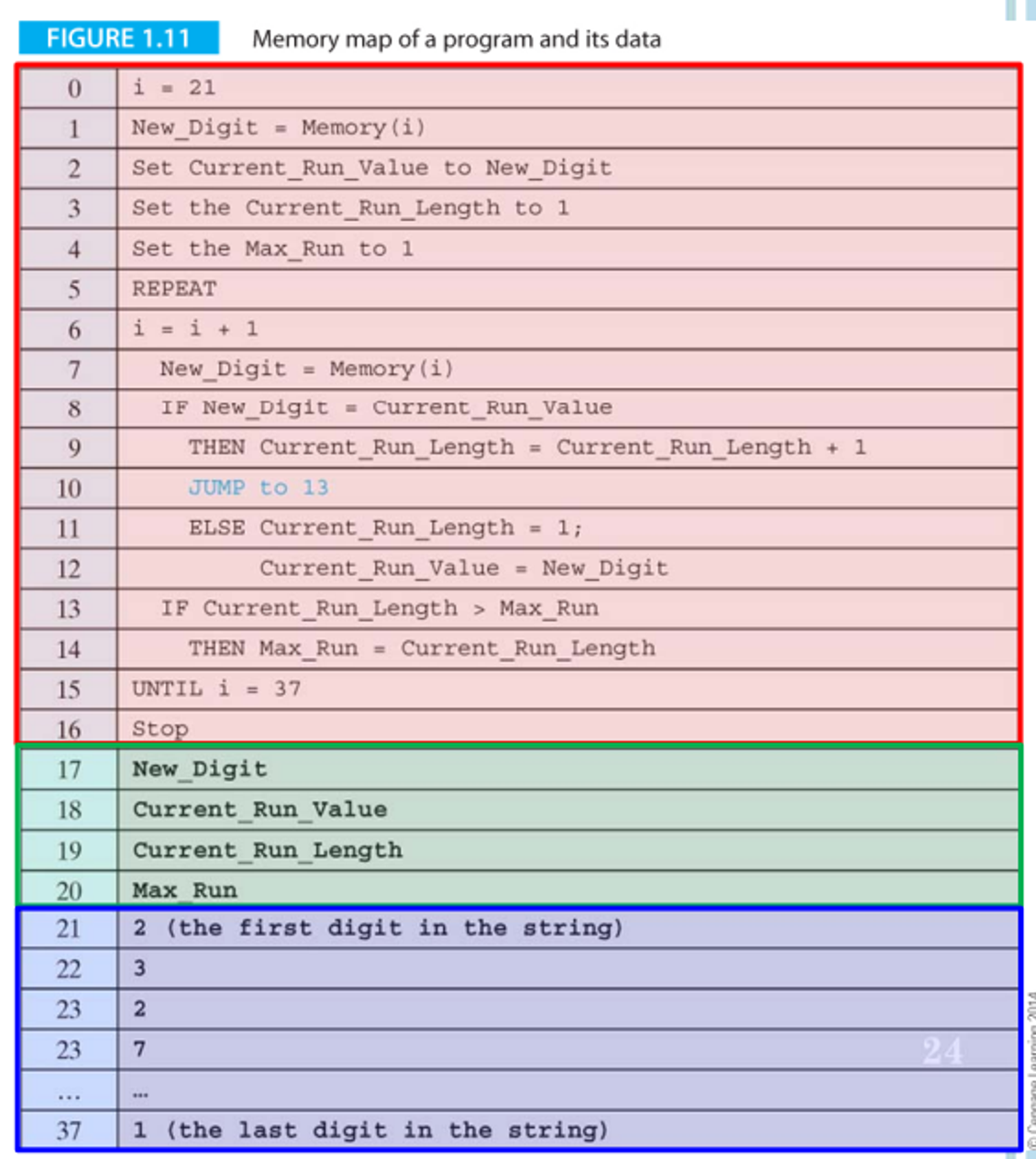
In this program, we have constants (values that don’t change), variables (values that do change) and symbolic names (names given to constants/variables to make them easier to use)
All of these pieces of information have a value and a location in memory, called the address
Now, let’s say we want to increment Max_Run; in this case, we can’t just say Max_Run = Max_Run + 1, because the computer only sees the address, so you’d end up with 20 + 1 = 21
- This distinction becomes important when we talk about pointers (variables with addresses as values)
Register Transfer Language
Register Transfer Language (RTL) is a way we can deal with these registers in an easy to interpret manner
In this notation, square brackets indicate the contents of a location in memory
- For example, [15] = Max_Run means that the content of memory location 15 is equal to the value of Max_Run, i.e. an initialization
The left arrow ← is a memory transfer
- Ex. [15] ← [15] + 1 means add 1 to the content of memory location 15 and place it in memory location 15
We can use pseudocode to express this fundamental action
Stored_program_machine
	Point to the first instruction in memory
	REPEAT
		Read the instruction at the memory location pointed at
		Point to the next instruction
		Decode the instruction just read from memory
		Execute the instruction
	FOREVER
End
For each instruction, we have to read from memory, so it’s best for us to minimize that by using less instructions
We also might need to read and write to memory, so we can expand our pseudocode as such
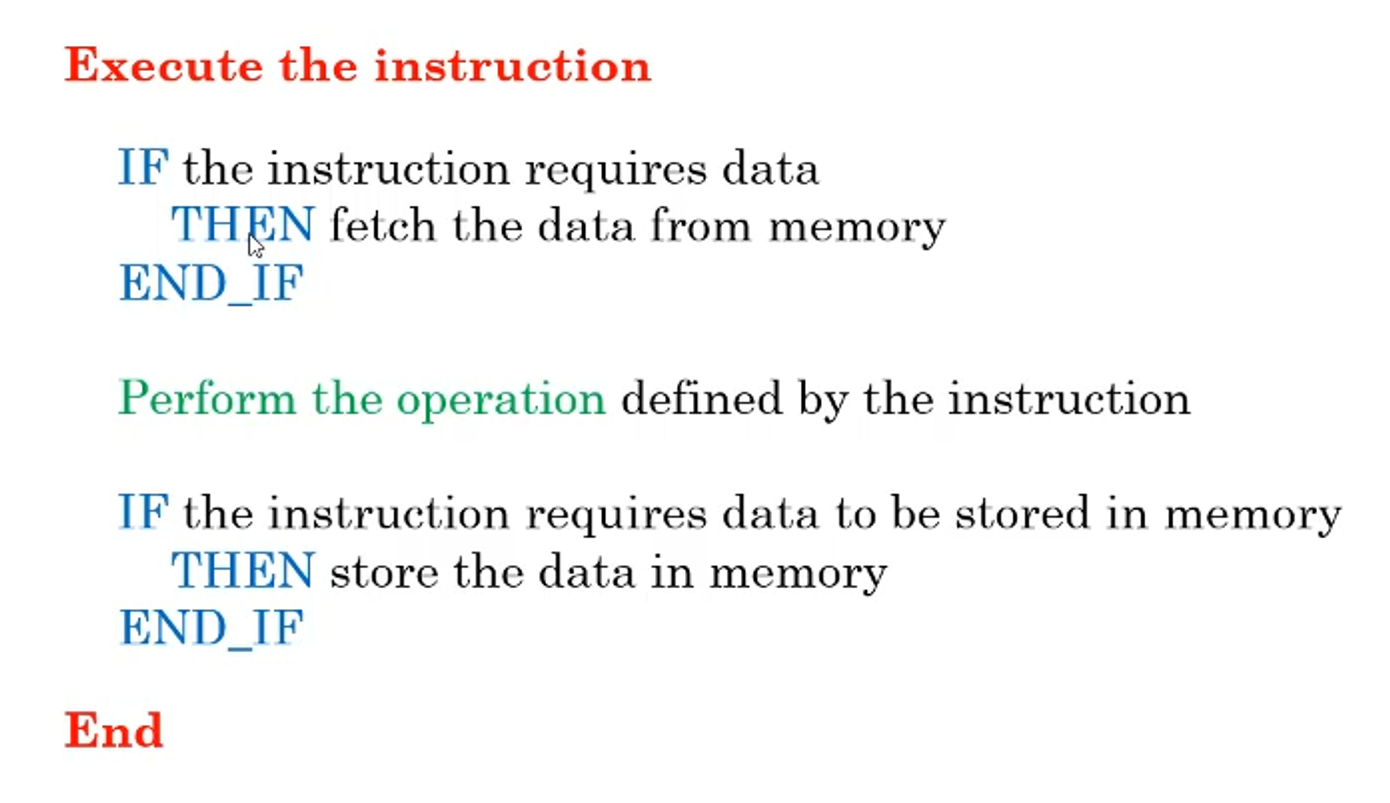
All in all, we have 3 situations of memory access
The address port will give an address and the control port will be either read or write, where memory will either be sent towards or away from memory
Assembly
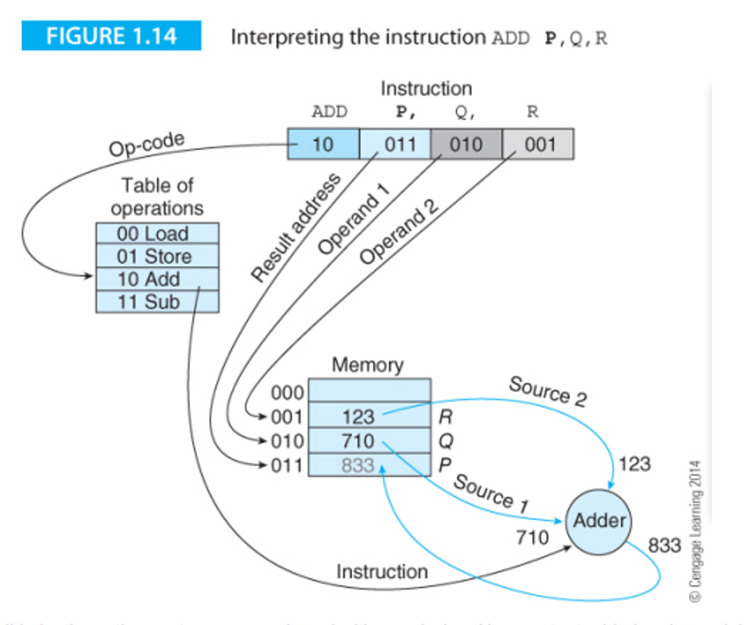
In Assembly, the language used to interact with the memory directly, there is a three-address format
This format goes Operation Address1 Address2 Address3, where Operation is the instruction and the address are locations of the three operands in memory
- In common use, we use bold font to indicate the destination address
For example, ADD P, Q, R will add Q and R and store it in P
- This can also be done in RTL notation: [Address1] ← Operation [Address2] [Address3]
The command interpretation looks something like this
We also have two-address format, Operation Address1 Address2, where address1 is a source and destination
The problem with this, however, is that one of the operands is overwritten, which you might not want, but you also gain the benefit of needing less memory reads
Bus
The bus, as we’ve mentioned before, is the highway system connecting all the functional parts of a computer, as well as external peripherals such as keyboards
Without a bus, the connections are all over the place and are hard to manage, while the bus makes the structure orderly in nature
You can also have more than one bus, which will allow for parallel operations since the two busses would be independent
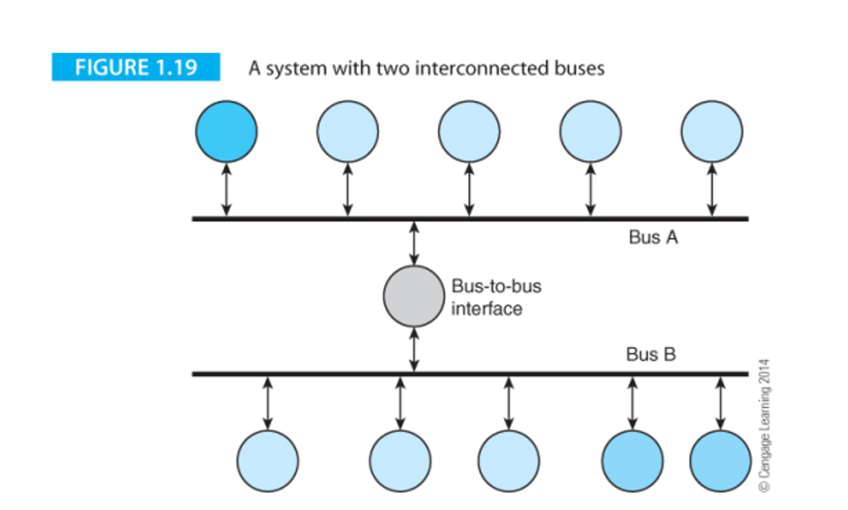
The bus has three ways of being described: the width (number of parallel data paths, ex. 64-bit bus carries 64 bits at once), the bandwidth (rate of information transportation, bytes/second) and the latency (time between data transfer request and data transmission completion)
Computer Arithmetic
As you may know, computer data is based on bits (0s and 1s) that represent low and high voltage in wires
- Ex. 0010 means 3
A convention we used is calling a unit of 8 bits a byte
Every time you introduce a bit to a sequence, you double the number of possibilities, so 2 bits has 4 values, 3 bits has 8 values, etc.
Binary and decimal notation uses Hindu-Arabic positional notation, meaning an n=digit number N is represented as such
\[N = a_{n-1}a_{n-2}...a_i...a_1a_0\]The value of N in this case would also depend on the base b, so the true value of N would be as follows
\[N=a_{n-1}b^{n-1} + a_{n-2}b^{n-2} + ... + a_1b^1 + a_0b^0\]Since binary is base 2, we will have b = 2
For example, with the number 0100 in binary, we say $0 + 2^3 + 0 + 0$
But what about fractions? In that case, we can extend our definition by saying there’s n digits to the left of the radix point (a.k.a. decimal point) and m digits to the left
From there, we can expand our general definition
\[N = a_{n-1}a_{n-2}...a_1a_0a_{-1}...a_{-m}\]Representing the true value goes the same way
This approach gives a good approximation, but it can lead to problems converting between bases, which are referred to as floating point errors
Operations
Basic operations in base 2 work similarly to the way they do in base 10
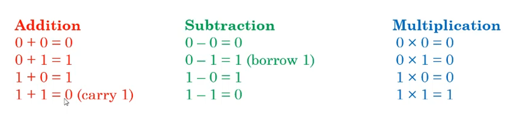
This makes adding larger numbers easy too, since you just use the same elementary school methods
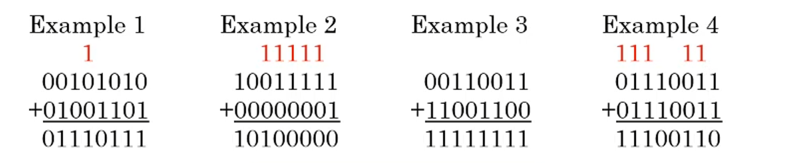
- Same logic applies to subtraction and multiplication, just do what you did in elementary school
The slight difference comes from multiplication, where we add partial products onto the final product as we go to save on memory
- Division is a little more complicated, but we will get into that later
Describers
With numbers, we have some ways of describing them
Range is the variation between the largest and the smallest value (for 8 bits, this would be 0-255)
Precision is a measure of how precise we can represent a number (pi can’t be represented in full in a finite space, so we can use a number of significant figures to represent it)
Accuracy is the difference between the representation and its actual value (if you say you’re 6’0 (183cm) when you’re actually 5’7 (170cm), this is an error of 5 inches (13cm))
- Note that this is different from accuracy
This is good and all, but how do we actually interpret these? Well, that would entirely depend on what the data is
ASCII
If the data is characters, we can use ASCII (American Standard Code for Information Interchange) which represents 128 characters from both the Latin alphabets and Arabic numeral system, as well as special characters like NULL
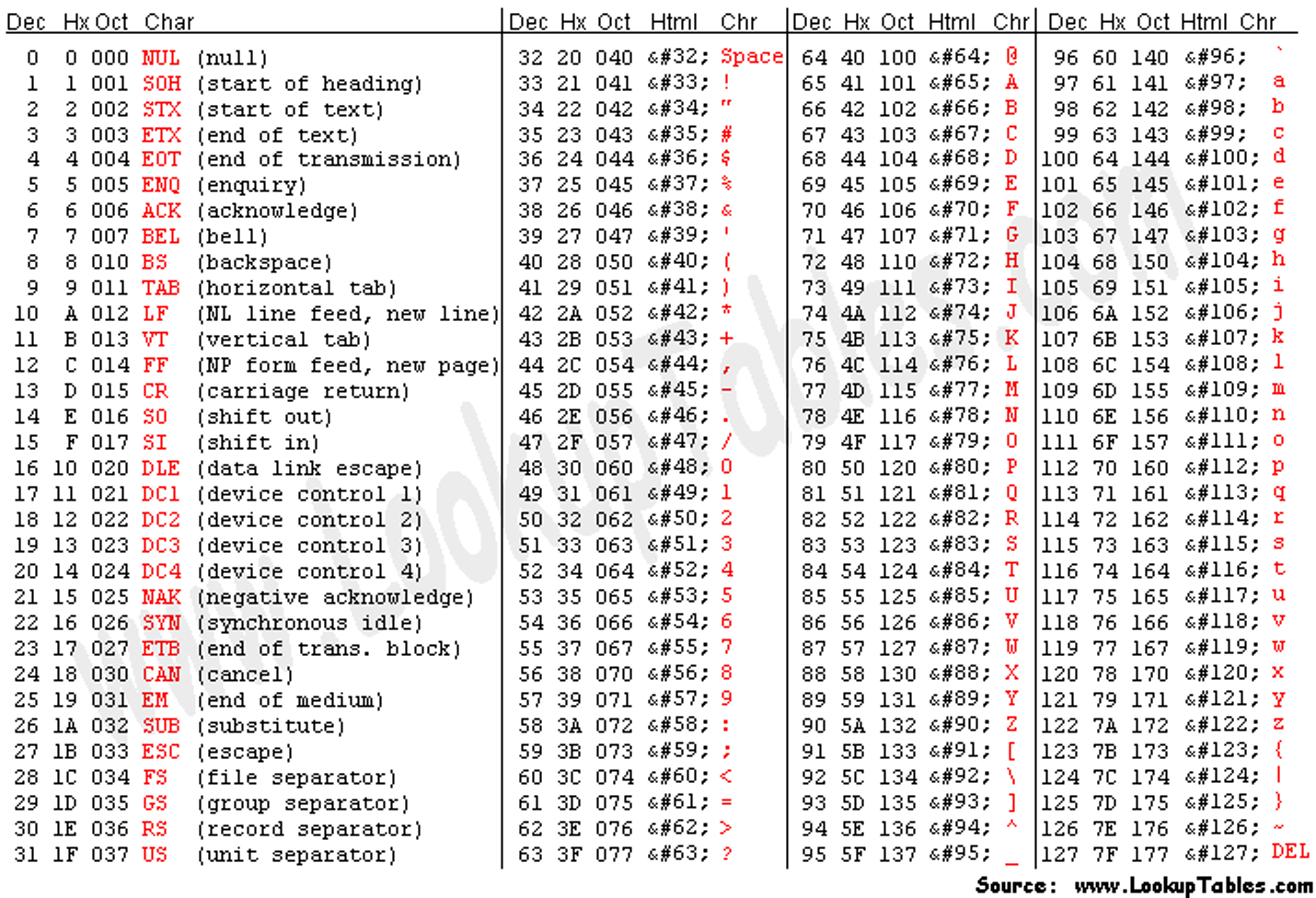
- There’s also UTF-8 and other standards for more complicated characters, but this is outside the scope of this course
This table also includes hex (hexadecimal) values, which is base 16 and is represented as 0-F
This behaves the same way as base-2 and base-10 as previously described
Flow Control and Encoding
Encoding of Branch Instructions
Branch instructions, like other instructions, are stored in a 32 bit address with the following division
- Bits 31-28 are the branch condition
- 27-25 are 101 in that order
- 24 is the L-bit which determines link (0 for a regular branch and 1 for a branch w/ link)
- The rest are a signed word offset (converted to a real byte address by left shifting twice)