Render Pipeline
Now that we’re heading into 3D, it’s important that we know how OpenGL actually renders objects and in what order
The pipeline follows 5 basic steps
- Vertex specification
- Vertex processing
- Vertex post-processing
- Primitive assembly
- Clipping
- Face culling
- Rasterization
- Sample Processing
- Depth testing, blending, etc.
Vertex Specification
Vertices are, at their core, points in space used to generate primitives
The only required attribute for these is position (glVertex), but there are others used to build the broader primitives
- glColor
- glNormal
- glTexCoord (for textures)
Since OpenGL is a state machine, vertex attributes like glColor persist and are applied to evert vertex specified with each glVertex call
For the texture, we’re essentially covering triangles with an image rather than a color
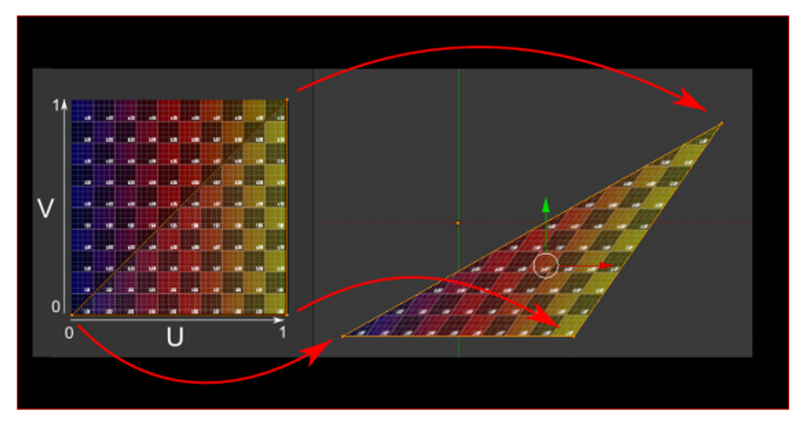
The texture coordinates are a pair of floats in the range $[0,1]$, often called $(u,v)$, which map to the width and height of the texture, respectively
The texture is then squished onto the image according to the triangle’s vertices to fit onto the triangle
Fixed Functions
The fixed function pipeline, a layer in between vertex specification and assembly, defines default behaviour for vertices, basically consisting only of matrix multiplication (GL_MODELVIEW → GL_PROJECTION)
- It’s consider fixed because it has no programmatic capabilities
After this, we get to primitive assembly
Primitive Assembly & Face Culling
Primitive assembly is the process of breaking down a vertex stream into a sequence of base primitives (points, lines and triangles)
- Face culling is done to remove triangles whose front face is or is not facing the camera
With winding order and glFrontFace, we specify whether the front face has vertices circling clockwise or counter-clockwise around the center
We can then enable face culling with glEnable(GL_CULL_FACE) and then well it which faces to cull, either front towards the camera (glCullFace(GL_FRONT)), back or both (GL_BACK, GL_FRONT_AND_BACK)
Rasterization & Attribute Interpolation
Rasterization is the process of converting base primitives to fragments, providing all the information needed to color a pixel, including position, depth, color and other attributes
What we didn’t color is interpolations, which is the process that rasterization uses to turn vertex attributes into the values for each fragment
Interpolation is used to interpolate multiple vertices’ attributes across all fragments between those vertices, using a simple lerp between the attributes of each vertex
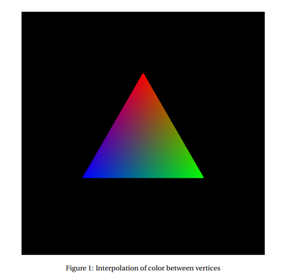
However, since a triangle has three vertices, it’s not a simple lerp, but rather a weighted average based on the distance between a fragment’s position and each of the vertices
For an example, if a triangle has all three vertices set to a different color, the result fragments vary between combinations of those colors
This is essentially how texture mapping works, since each fragment gets an interpolated value of texture coordinates
- From here, we access a texture’s pixel (texel) to determine the color of the fragment
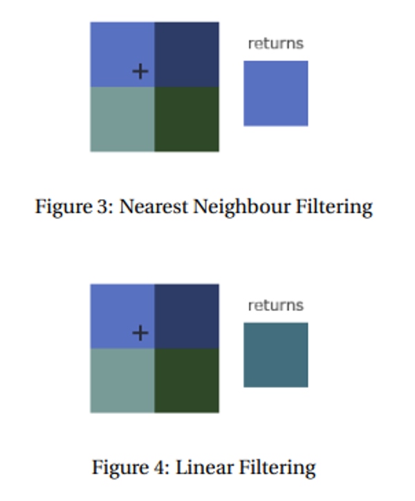
We still need to handle discrete pixel coloring, which we do with texture filtering
Two strategies exist: nearest neighbour and bilinear/linear filtering
Sample Processing
Now that we have out fragments we need to draw them out to the frame buffer, but it’s possible for different primitives to overlap, allowing more than one fragment to cover the same pixel
What we mainly need to consider is depth and blending; without enabling these, whatever is drawn last would be displayed
- We enable these with glEnable
Depth
When a fragment is determined to cover a pixel, it first checks if that pixel is already covered, color that pixel if it isn’t
If it is, either color it again (overdraw) or discard the current fragment and leave the pixel unmodified
The choice to overdraw depends on the depth test, using the z coordinate of the fragment after perspective divide to determine whether the current fragment passes or not
The values that pass a depth test depend on the depth function, using glDepthFunc
The options include
- GL_LESS: if the depth value is less than the previous one, depth test passes
- GL_GREATER: same thing but in reverse
The actual comparison is facilitated through the depth buffer, so when we draw fragments to the frame buffer, we also draw them to the depth buffer in a one-to-one correspondence
Blending
Blending allows fragments to be blended and mixed together to get interesting effects, using the blend function to determine how that fragment’s color is mixed with the existing pixel color in the frame buffer
Many of these functions exist, but they all specify a weighted sum of the course color and the destination color
Letting $f_{s,R}, f_{s,G}, f_{s,B}, f_{s,A}$ be the scale factors for the source color channels $R,G,B,A$ and $f_{d,R}, f_{d,G}, f_{d,B}, f_{d,A}$ be the destination color channels, the new color is calculated by the following
\[new_i = S_if_{s,i}+D_if_{d,i}\]- $new_i$ is clamped so as to not overflow the max
We specify the blend function with glBlendFunc with the most common being glBlendFunc(GL_SRC_ALPHA, GL_ONE_MINUS_SRC_ALPHA) and the default being glBlendFunc(GL_ONE, GL_ZERO)
- The most common one mimics the effect of translucent objects
Clearing
We can clear our buffers and write a solid color to everywhere with glClear, with glClearColor specifying a default color and glClearDepth to specify a default depth (default is 1)
Shaders
An important part of graphics is shaders, which specify textures, lights, material, etc.
We can use GLSL to write these shaders, which is a programming language similar to C, executed as a shader object, linking to become a program
GLSL doesn’t have the same capacity as C, but it does include more stuff, including vectors, matrices, textures and more
The basic program consists of 4 main parts
#version xyz core //version code

in vec3 fromPreviousShader //input variables

out vec3 toNextShader //output variables

void main() { //main function
	toNextShader = fromPreviousShader;
}
You can also just write these as functions and call them from main
Vertex Shaders
Vertex shaders are executed for each vertex in a draw call, with the inputs coming from vertex specification and any other attributes
- You NEED to have these attributes if the shader expects it, otherwise you’re screwed
The outputs are then passed to the next stage (other shaders if they’re specified, post-processing if they’re not)
We need a vertex position at minimum, which is specified in clip space, so for vertices in local coordinates, the output should be $PVMv_{local}=v_{clip}$
- The shader usually does this itself but we can always do it on the client side
Tesselation & Geometry Shaders
These generate more primitives from existing primitives as a sort of primitive pre-assembly and extension, where tesselations sub-divide primitives and geometries create new vertices
Fragment Shaders
To shade fragments, we get some inputs by default that don’t need to be explicitly mentioned
- vec4 gl_FragCoord, the (x,y) position of the fragment in window space
- bool gl_FrontFacing, says whether or not the fragment is facing the camera or not
- Anything else interpolated from vertex attributes in the vertex shader
The output must include at least one color so that we can see it, traditionally using vec4 gl_FragColor as a built-in
- This is deprecated in newer versions, so we should output a different variable that specifies what to draw
If you noticed, the next shader must take input values that are outputted from the previous shader, which is known as interface matches
Shaders in Practice
To actually use shaders, we specify the code as a string, which is compiled into a shader object and linked to programs at runtime
The basic steps are as follows
- Create a shader object with glCreateShader(GL_SHADER_TYPE), returning a unique ID
- Specify the source code with glShaderSource(shaderID, count, stringArray, lengthArray)
- Compile the shader with glCompileShader(shaderID)
Usually stringArray is just one string, but OpenGL allows for several strings to be passed and a concatenation is produced, creating the source code
- lengthArray is the length of the string (we can use NULL to specify that the strings are NULL-terminated)
Now we don’t have a program yet, so let’s do that
- Create the program with glCreateProgram()
- Attach the objects with glAttachShader(programID, shaderID)
- Link the program with glLinkProgram(programID) to create an executable
This state is then fixed until we call glLinkProgram again
Using Shaders
Now we have a program, but we still need to use this, so we need to look at vertex specification
Each attribute in a vertex shader is given a location, so we need to tell OpenGL where they are for each draw call
in vec3 vertexPosition_modelspace;
in vec4 color_in;

void main() { ... }
In the above, vertexPosition_modelspace implicitly has location 0 and color_in, location 1. We can also explicitly give a variable a location by prefacing it with layout(location = i).
layout(location = 0) in vec3 vertexPosition_modelspace;
layout(location = 1) in vec4 color_in;

void main() { ... }
Let’s say we have parallel arrays of floats for the vertex attributes of position and color. For example, vertex i should have (x, y, z) position:
(vertices[3*i], vertices[3*i + 1], vertices[3*i + 2])
and RGBA color:
(colors[3*i], colors[3*i + 1], colors[3*i + 2], colors[3*i + 3]).
We must enable a vertex attribute at a specific location, and then provide a pointer to that attribute data.
glEnableVertexAttribArray(0); // enable location 0
glVertexAttribPointer(
    0,                  // attribute location in shader
    3,                  // this attribute has 3 coordinates
    GL_FLOAT,           // type
    GL_FALSE,           // normalized?
    0,                  // stride
    vertices            // vertex attribute pointer
);

glEnableVertexAttribArray(1); // enable location 1
glVertexAttribPointer(
    1,                  // attribute location
    4,                  // this attribute has 4 coordinates
    GL_FLOAT,           // type
    GL_FALSE,           // normalized?
    0,                  // stride
    colors              // vertex attribute pointer
);
We need to recall that our vertices are assumed to be in clip space, so we need to translate ourselves
Luckily, GLSL provides us a way to just import the matrix that we’re using
-
Find the uniform: we get the location of a uniform variable of name
varNameusingglGetUniformLocation(ProgramID, "varName"). This returns a unique ID for the variable in the program. This find only needs to be done one time, after the program is linked. -
Set the uniform: we use
glUniform*(uniformID, ...)
With this shader:
in vec3 vertexPosition_modelspace;
uniform mat4 MVP;

void main() {
    gl_Position = MVP * vertexPosition_modelspace;
}
The following sets the uniform:
glm::mat4 Projection = glm::perspective(glm::radians(45.0f), screenW/screenH, 0.001f, 1000.0f);
glm::mat4 V = glm::lookAt(eye, center, up);
glm::mat4 M = glm::mat4(1.0f); // identity
glm::mat4 MVP = Projection * V * M;

GLuint MatrixID = glGetUniformLocation(ProgramID, "MVP");
glUniformMatrix4fv(MatrixID, 1, GL_FALSE, &MVP[0][0]);
Textures Again
We can use texture objects similarly to how we use shader objects, complete with texture storage
-
Bind the texture object to a texture target. Possible targets are,
GL_TEXTURE_1D,GL_TEXTURE_2D,GL_TEXTURE_3D, etc. depending on the dimensions of the image to load. This is done withglBindTexture(textureTarget, textureID). -
Load the bitmap image into a texture target:
glTexImageXDmust useGL_TEXTURE_XDas its target, where X is one of 1, 2, 3. -
Generate Mipmaps. Just call
glGenerateMipmap(GL_TEXTURE_XD). Otherwise your texture won’t work. -
After loading, one should unbind the texture object. Since OpenGL is a state machine, we want to avoid accidental side-effects of leaving a texture object bound. We unbind an object to a target by calling
glBindTexture(GL_TEXTURE_XD, 0).
Texture units can also be defined, which are slots used to access texture data in draw calls.
-
Set which texture unit is active by calling
glActiveTexture(GL_TEXTUREi). -
Enable a texture target within the active unit. We call
glEnablewith one ofGL_TEXTURE_1D,GL_TEXTURE_2D,GL_TEXTURE_3D, etc. to get that texture enabled for subsequent draw calls. -
Bind a texture object to a texture target. We may have previously bound a texture object to a texture target in order to fill it with data, but now we have to bind it again so that the draw calls can read the texture data.
-
Do your draw calls (details below).
-
Unbind the texture object.
A vertex shader should input and output texture coordinates as part of the vertex specification. After interpolation, each fragment will have its own texture coordinates. Now, the fragment shader should use those texture coordinates to actually read data from the texture. This is the job of the sampler.
#version 330 core

in vec2 uv2;
uniform sampler2D tex;

void main() {
    gl_FragColor = texture(tex, uv2);
}
In GLSL, we use the texture() function to read the color data from a texture’s texture storage at a particular location. If the texture is 2D, we need 2D coordinates, etc. The uniform variable tex is actually a simple integer to describe which texture unit to read from. By default, it is 0.
If we want to read from a texture unit other than GL_TEXTURE0, we have to set the uniform in the shader appropriately. In our client code, we get the uniform location from the linked program object and then set its value:
GLuint texID = glGetUniformLocation(ProgramID, "tex");
glUniform1i(texID, i); // i is an integer corresponding to GL_TEXTUREi